Connecting LAN Interfaces
The device's Gigabit Ethernet LAN ports (1000Base-T) can be connected to network equipment and entities such as computers, switches, and IP phones. These ports support half- and full-duplex modes, auto-negotiation, and straight or crossover cable detection.
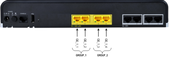
The Ethernet ports can operate in pairs (Ethernet Groups) to provide 1+1 port redundancy, where one port serves as the active port while the other as standby. When the active port fails, the device switches to the standby port. By default, the Ethernet ports are grouped into pairs, as shown in the following figure with the port string names used for software configuration. You can change this port assignment, including assigning only a single port to an Ethernet Group. For more information, refer to the User's Manual.
Default Ethernet Port Groups and Port String Names for Software Configuration
The Ethernet cabling specifications include the following:
| ■ | Cable: Straight-through, Category (Cat) 5e cable |
| ■ | Connector: Standard RJ-45 |
| ■ | Connector Pinouts: |
RJ-45 Connector Pinouts for GE
|
Pin |
Signal Name |
|---|---|
|
1 |
Ethernet signal pair (1000Base-T) |
|
2 |
|
|
3 |
Ethernet signal pair (1000Base-T) |
|
6 |
|
|
4 |
Ethernet signal pair (1000Base-T) |
|
5 |
|
|
7 |
Ethernet signal pair (1000Base-T) |
|
8 |
|
|
Shield |
Chassis ground |
| ➢ | To connect the device to the LAN: |
| 1. | Connect one end of a straight-through RJ-45 Cat 5e or Cat 6 cable to the LAN port, located on the rear panel and labeled GE LAN. |
Cabling LAN Ports
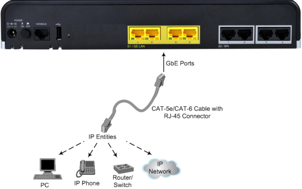
| 2. | Connect the other end of the cable to a network device or entity. |
| 3. | For 1+1 LAN protection, repeat steps 1 and 2 for the standby port, but connect it to another network (but in the same subnet). |
Ethernet port interface cabling must be routed only indoors and must not exit the building.